

and possibility to request for custom firmware
Computer controlled by USB connection
Seamlessly integrates with Lambert Instruments’ intensifier attachments
For integration into a larger system or for automated measurements, the gain control unit for automated systems lets you control the settings of the intensifier attachment. The control unit uses standard TTL and analog signals for communication, allowing the user to switch the intensifier on or off, alter the gain and the anode current limit of the image intensifier without the need of software integration.
Time resolved imaging
Rapid Gate switching to improve dynamic range
To be used with Lambert Instruments’ Intensifier Attachments.
Image Intensifier Gain
By increasing the image intensifier gain, the incoming light intensity will be boosted more, resulting in a brighter image. The intensifier control for automated systems lets you control the gain of the image intensifier.
Anode Current Limit
To protect the fragile image intensifier from being damaged by overexposure, the anode current limiter can be used to set a limit for the acceptable anode current. If the anode current exceeds this value, then the image intensifier will be switched to a safe mode.
Compatibility
The gain control unit for automated systems is compatible with our intensifier attachments: HiCATT and TRiCATT
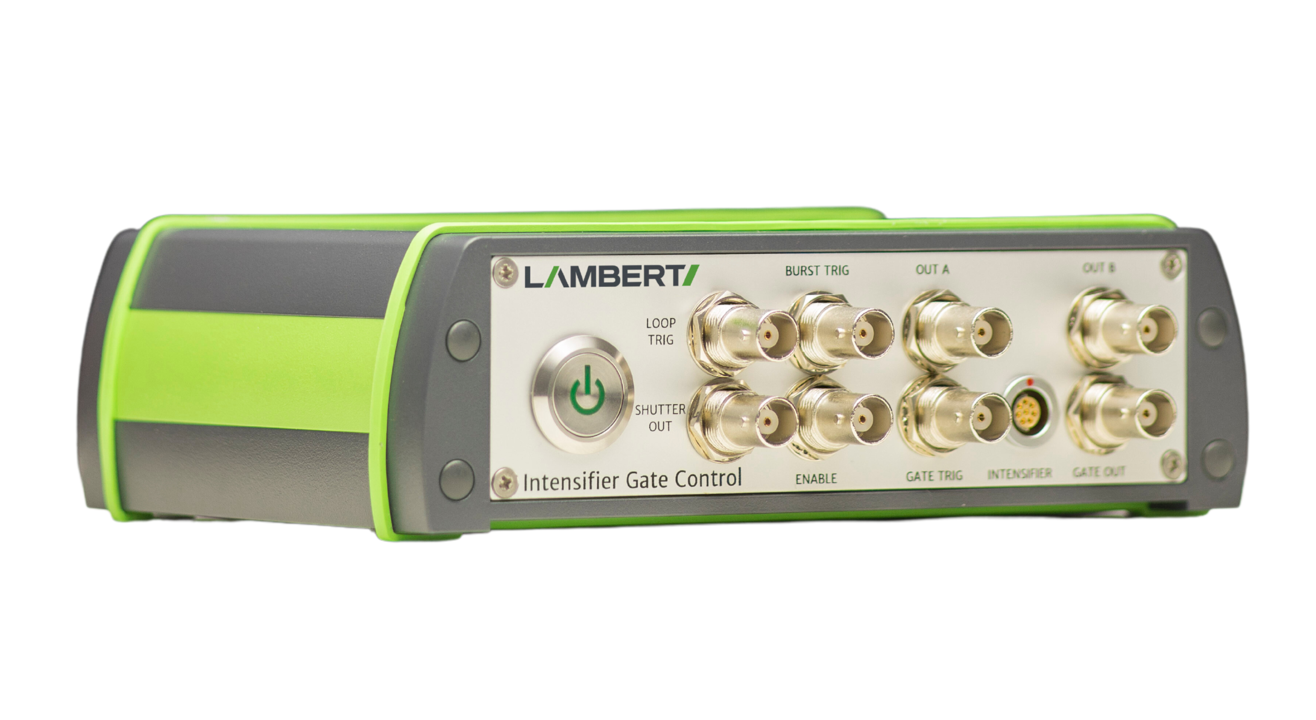
A synchronisation signal is needed in order to create an output at the three outputs of the intensifier gate control. This signal can originate from different sources:
External source: For instance a signal from a frame grabber or a connected camera.
Software command
Internal sync source: Gives synchronisation pulses with a fixed frequency. Can generate pulses at frequencies between 0.5 Hz and 4 MHz.
When using an external synchronisation source, the following modes are available:
– Synchronise with rising edge of external input pulse
– Synchronise with falling edge of external input pulse
– Follow external input pulse
| Timing Resolution | 250ps |
|---|---|
| Jitter Pulse Width | <250 ps RMS |
| Jitter Delay | <250 ps RMS |
| Sync with falling/rising edge | Follow external output post | |
|---|---|---|
| Pulse width /delay range | 10ns – 10s | 10ns – 10s |
| Timing resolution (Step size) | 10ns | 10ns |
| Jitter pulse width | <10ps RMS | <10ps RMS |
| Jitter delay | <10ns RMS | <250ns RMS |
| Insertion delay | 30ns | 20ns |
Leonard Springerlaan 19
9727 KB Groningen
The Netherlands