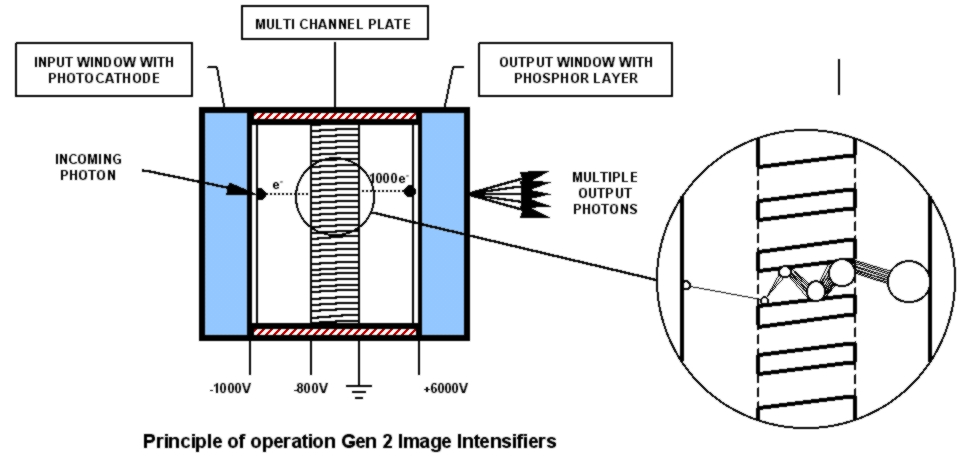
In the second-generation image intensifier a so-called Micro-Channel Plate or MCP is added, improving the gain of the image intensifier enormously. The MCP is placed between the cathode and the anode and acts as an electron multiplier.
The MCP is a 0.5 mm thick plate with millions of 6 micron wide holes. An accelerated electron coming from photocathode will be accelerated towards the MCP. When the electron hits the wall of one of the MCP channels it will spawn secondary electrons. Due to the voltage over the MCP, these electrons will also be accelerated, and hit the surface of the MCP in their turn. Again spawning new (tertiary) electrons. This process is repeated several times, resulting in an electron gain far higher (several thousand times higher) than in first generation intensifiers.
When an electron leaves the MCP, it is propelled to the phosphor screen where it will generate multiple photons. The overall gain of an image intensifier is up to ten thousand. With two or three MCPs amplifications up to 10 million times gain is possible. The gain of the image intensifier can even be controlled by changing the voltage over the MCP.
GATING THE IMAGE INTENSIFIER
An important feature of the MCP, and therefore the second-generation image intensifier, is that it can be gated. Gating the image intensifier offers a whole new possibility of using the image intensifier as an ultra fast (electro-optical) shutter. Gating is achieved by controlling the photocathode voltage of the image intensifier, creating a shutter with effective exposure times down to a few nanoseconds.
By applying a negative voltage to the photocathode, typically -200 V with respect to the MCP input, photoelectrons are generated in the photocathode. They are emitted and accelerated to the MCP to be multiplicated. In this situation the image intensifier is “gated on”. When applying a small positive voltage to the photocathode, typically 50 V with respect to the MCP, the photoelectrons can not be emitted and the intensifier is “gated off”. With this gating option the input light range is extended significantly and it offers unique options for time resolved experiments.
In the Lambert Instruments Fluorescence Attachment, a second-generation image intensifier is used as a detector. The image intensifier, combined with a CCD camera, is attached to a widefield fluorescence microscope. The photocathode of the intensifier is located in the image (focal) plane of the microscope. In the frequency domain LIFA, the photocathode is switched from positive to negative at the same frequency as the light source is modulated.
Furthermore gating can be used to reduce or prevent the effect of motion blur when capturing fast moving objects. In our Intensified cameras gating is standard synchronised with the exposure period of the CCD or CMOS sensor.
ADVANTAGES
Fibre-optic/glass/quartz/MgF2 input windows
Many photocathode types from UV to NIR
High gain
Fast shuttering is possible (gating)
Good over-illumination protection
Maximum output brightness control
Wide gain control range
Many types of output phosphors
Distortion free
DISADVANTAGES
Limited intra-scene dynamic ranges
Low maximum output brightness for fast phosphors
No de-magnifying models
MCP introduces extra noise